
Pockels cell drivers PCD with energy-efficient power supplies HV
High repetition rate and high voltage Pockels cell drivers with energy-efficient power supplies
Ekspla’s Pockels cell drivers are optimal for BBO, RTP, KD*P, KTP, LiNbO3, CdTe Pockels cells. They can provide high voltage output pulses up to 9.8 kV, repetition rates up to 6 MHz, electrical pulse rise times as short as 5.5 ns, minimal pulse durations as low as 0 ns and maximal pulse durations with no limit.

Features
- HV repetition rates up to 6 MHz
- HV output pulse amplitude up to 9.8 kV
- Electrical HV rise / fall times typically as low as 5.5 ns at 6pF load
- HV pulse durations from 0 ns to infinity
- Amplitude modulation of independent HV output pulses
- Designed for BBO, RTP, KD*P, KTP, LiNbO3, CdTe Pockels cells
- Complimentary HV power supplies for each driver version
- Drivers can be tailored to precisely meet OEM customer’s needs
- Fast turnaround times between inquiry, prototyping and high-volume manufacturing stages.
Applications
EKSPLA’s Pockels cell drivers are optimal for pulse picking, mode-locking, cavity dumping and q-switching of the solid state femtosecond, picosecond and nanosecond lasers. Most popular fields of applications are:
- Industrial lasers
micromachining, welding and cutting - Medical lasers
ophthalmology, dermatology and surgery - Scientific lasers
fusion research, spectroscopy, and high-energy physics
Performance
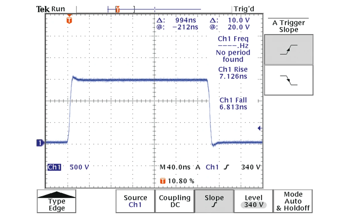
Typical output pulse shape.

Typical rising front of output pulse in detail.

Typical falling front of output pulse in detail.
| Model ¹⁾ | Repetition rate, max 2) | Output pulse amplitude, max | Pulse rise / fall times, typical 3) | Pulse duration range, min – max 4) | Power consumption, max 3) | Cooling method | Dimensions (L×W×H) | Drawing |
|---|---|---|---|---|---|---|---|---|
| PCD-UHR series | ||||||||
| PCD-UHR-50-3.6 | 50 kHz | 3.6 kV | < 7 ns | 100 – 5000 ns | 20 W | Conductive | 94×63×31 mm | Fig. 1 |
| PCD-UHR-50-3.6-C | 50 kHz | 3.6 kV | < 7 ns | 100 – 5000 ns | 20 W | Water | 114×73×50 mm | Fig. 2 |
| PCD-UHR-50-3.6-C-Option1 | 50 kHz | 3.6 kV | < 7 ns | 100 – 5000 ns | 20 W | Conductive or water | 116×68×42 mm | Fig. 3 |
| PCD-UHR-250-2.6 | 250 kHz | 2.6 kV | < 6 ns | 100 – 3900 ns | 40 W | Conductive or water | 116×63×38 mm | Fig. 1 |
| PCD-UHR-250-2.6-C | 250 kHz | 2.6 kV | < 6 ns | 100 – 3900 ns | 40 W | Water | 114×73×50 mm | Fig. 2 |
| PCD-UHR-250-2.6-C-Option1 | 250 kHz | 2.6 kV | < 6 ns | 100 – 3900 ns | 40 W | Conductive or water | 116×68×42 mm | Fig. 3 |
| PCD-UHR-250-3.6 | 250 kHz | 3.6 kV | < 7 ns | 100 – 3900 ns | 75 W | Conductive or water | 116×63×38 mm | Fig. 1 |
| PCD-UHR-250-3.6-C | 250 kHz | 3.6 kV | < 7 ns | 100 – 3900 ns | 75 W | Water | 114×73×50 mm | Fig. 2 |
| PCD-UHR-250-3.6-C-Option1 | 250 kHz | 3.6 kV | < 7 ns | 100 – 3900 ns | 75 W | Conductive or water | 116×68×42 mm | Fig. 3 |
| PCD-UHR-400-1.5 | 400 kHz | 1.5 kV | < 5.5 ns | 100 – 2400 ns | 20 W | Conductive or water | 116×63×38 mm | Fig. 1 |
| PCD-UHR-400-1.5-C | 400 kHz | 1.5 kV | < 5.5 ns | 100 – 2400 ns | 20 W | Water | 114×73×50 mm | Fig. 2 |
| PCD-UHR-400-1.5-C-Option1 | 400 kHz | 1.5 kV | < 5.5 ns | 100 – 2400 ns | 20 W | Conductive or water | 116×68×42 mm | Fig. 3 |
| PCD-UHR-500-2.6 | 500 kHz | 2.6 kV | < 6.5 ns | 100 – 1900 ns | 90 W | Conductive or water | 116×63×38 mm | Fig. 1 |
| PCD-UHR-500-2.6-C | 500 kHz | 2.6 kV | < 6.5 ns | 100 – 1900 ns | 90 W | Water | 114×73×50 mm | Fig. 2 |
| PCD-UHR-500-2.6-C-Option1 | 500 kHz | 2.6 kV | < 6.5 ns | 100 – 1900 ns | 90 W | Conductive or water | 116×68×42 mm | Fig. 3 |
| PCD-UHR-1000-1.8 | 1 MHz | 1.8 kV | < 6 ns | 100 – 900 ns | 80 W | Conductive or water | 116×63×38 mm | Fig. 1 |
| PCD-UHR-1000-1.8-C | 1 MHz | 1.8 kV | < 6 ns | 100 – 900 ns | 80 W | Water | 114×73×50 mm | Fig. 2 |
| PCD-UHR-1000-1.8-C-Option1 | 1 MHz | 1.8 kV | < 6 ns | 100 – 900 ns | 80 W | Conductive or water | 116×68×42 mm | Fig. 3 |
| PCD-UHR-2000-1.5 | 2 MHz | 1.5 kV | < 7 ns | 100 – 400 ns | 120 W | Conductive or water | 116×63×38 mm | Fig. 1 |
| PCD-UHR-2000-1.5-C | 2 MHz | 1.5 kV | < 7 ns | 100 – 400 ns | 120 W | Water | 114×73×50 mm | Fig. 2 |
| PCD-UHR-2000-1.5-C-Option1 | 2 MHz | 1.5 kV | < 7 ns | 100 – 400 ns | 120 W | Conductive or water | 116×68×42 mm | Fig. 3 |
| PCD-UHR-I-250-5.2-C | 250 kHz | 5.2 kV | < 8.5 ns | 100 – 5000 ns | 100 W | Conductive or water | 158×49×81 mm | Fig. 4 |
| PCD-UHR-I-300-4.6-C | 300 kHz | 4.6 kV | < 8 ns | 100 – 5000 ns | 100 W | Conductive or water | 158×49×81 mm | Fig. 4 |
| PCD-UHR-I-350-4-C | 350 kHz | 4 kV | < 7.5 ns | 100 – 5000 ns | 100 W | Conductive or water | 158×49×81 mm | Fig. 4 |
| PCD-UHR-I-1000-3.0-C | 1 MHz | 3 kV | < 7.5 ns | 100 – 5000 ns | 120 W | Conductive or water | 158×49×81 mm | Fig. 4 |
| PCD-UHR-II-150-7.0 | 150 kHz | 7 kV | < 9.5 ns | 100 – 5000 ns | 110 W | Conductive | 148×74×33 mm | Fig. 5 |
| PCD-UHR-II-250-7.0-C | 250 kHz | 7 kV | < 9.5 ns | 100 – 5000 ns | 200 W | Conductive or water | 172×77×51 mm | Fig. 6 |
| PCD-UHR-II-1000-3.8-C | 1 MHz | 3.8 kV | < 6 ns | 100 – 5000 ns | 230 W | Conductive or water | 172×77×51 mm | Fig. 6 |
| PCD-UHR-II-1000-4.0-C | 1 MHz | 4 kV | < 9.5 ns | 100 – 5000 ns | 210 W | Conductive or water | 172×77×51 mm | Fig. 6 |
| PCD-UHR-III-500-7.2-C | 500 kHz | 7.2 kV | < 8 ns | 100 – 1900 ns | 400 W | Water | 220×87×98 mm | Fig. 7 |
| PCD-UHR-III-2000-3.4-C | 2 MHz | 3.4 kV | < 8.5 ns | 100 – 400 ns | 360 W | Water | 220×87×98 mm | Fig. 7 |
| PCD-UHR-III-2500-3.1-C | 2.5 MHz | 3.1 kV | < 9.5 ns | 100 – 300 ns | 360 W | Water | 220×87×98 mm | Fig. 7 |
| PCD-UHR-III-3000-2.6-C | 3 MHz | 2.6 kV | < 8.5 ns | 100 – 233 ns | 325 W | Water | 220×87×98 mm | Fig. 7 |
| 2PCD-UHR series | ||||||||
| 2PCD-UHR-500-3.4-C | 500 kHz | 3.4 kV | < 7 ns | 0 – 1900 ns | 150 W | Water | 210×98×53 mm | Fig. 8 |
| 2PCD-UHR-1000-2.4-C | 1 MHz | 2.4 kV | < 6.5 ns | 0 – 900 ns | 180 W | Water | 210×98×53 mm | Fig. 8 |
| 2PCD-UHR-2000-1.6-C | 2 MHz | 1.6 kV | < 6 ns | 0 – 400 ns | 130 W | Water | 210×98×53 mm | Fig. 8 |
| 2PCD-UHR-II-300-3.4 | 300 kHz | 3.4 kV | < 7 ns | 0 – 1556 ns | 110 W | Conductive | 148×74×33 mm | Fig. 5 |
| 2PCD-UHR-II-500-3.4-C | 500 kHz | 3.4 kV | < 7 ns | 0 – 900 ns | 200 W | Conductive or water | 172×77×51 mm | Fig. 6 |
| 2PCD-UHR-II-1000-2.5-C | 1 MHz | 2.5 kV | < 7 ns | 0 – 400 ns | 170 W | Conductive or water | 172×77×51 mm | Fig. 6 |
| 2PCD-UHR-II-2000-1.8-C | 2 MHz | 1.8 kV | < 7 ns | 0 – 150 ns | 210 W | Conductive or water | 172×77×51 mm | Fig. 6 |
| 2PCD-UHR-II-2000-1.5-C | 2 MHz | 1.5 kV | < 6 ns | 100 – 900 ns | 215 W | Conductive or water | 172×77×51 mm | Fig. 6 |
| 2PCD-UHR-III-4000-1.7-C | 4 Mhz | 1.7 kV | < 10.5 ns | 100 – 300 ns | 360 W | Water | 220×87×98 mm | Fig. 7 |
| 2PCD-UHR-III-6000-1.3-C | 6 Mhz | 1.3 kV | < 9 ns | 100 – 233 ns | 350 W | Water | 220×87×98 mm | Fig. 7 |
| PCD-UHRS series | ||||||||
| PCD-UHRS-50-3.6 | 50 kHz | 3.6 kV | < 7 ns | 25 – 5000 ns | 20 W | Conductive | 94×63×31 mm | Fig. 9 |
| PCD-UHRS-50-3.6-C | 50 kHz | 3.6 kV | < 7 ns | 25 – 5000 ns | 20 W | Water | 114×73×50 mm | Fig. 11 |
| PCD-UHRS-50-3.6-C-Option1 | 50 kHz | 3.6 kV | < 7 ns | 25 – 5000 ns | 20 W | Conductive or water | 116×68×42 mm | Fig. 10 |
| PCD-UHRS-250-3.6 | 250 kHz | 3.6 kV | < 7 ns | 25 – 1000 ns | 75 W | Conductive or water | 116×63×38 mm | Fig. 9 |
| PCD-UHRS-250-3.6-C | 250 kHz | 3.6 kV | < 7 ns | 25 – 1000 ns | 75 W | Water | 114×73×50 mm | Fig. 11 |
| PCD-UHRS-250-3.6-C-Option1 | 250 kHz | 3.6 kV | < 7 ns | 25 – 1000 ns | 75 W | Conductive or water | 116×68×42 mm | Fig. 10 |
| PCD-UHRS-250-2.6 | 250 kHz | 2.6 kV | < 6 ns | 25 – 1000 ns | 40 W | Conductive or water | 116×63×38 mm | Fig. 9 |
| PCD-UHRS-400-1.5 | 400 kHz | 1.5 kV | < 5.5 ns | 25 – 625 ns | 20 W | Conductive or water | 116×63×38 mm | Fig. 9 |
| PCD-UHRS-500-2.6 | 500 kHz | 2.6 kV | < 6.5 ns | 25 – 500 ns | 90 W | Conductive or water | 116×63×38 mm | Fig. 9 |
| PCD-UHRS-500-2.6-C | 500 kHz | 2.6 kV | < 6.5 ns | 25 – 500 ns | 90 W | Water | 114×73×50 mm | Fig. 11 |
| PCD-UHRS-500-2.6-C-Option1 | 500 kHz | 2.6 kV | < 6.5 ns | 25 – 500 ns | 90 W | Conductive or water | 116×68×42 mm | Fig. 10 |
| PCD-UHRS-1000-1.8 | 1 MHz | 1.8 kV | < 6 ns | 25 – 250 ns | 80 W | Conductive or water | 116×63×38 mm | Fig. 9 |
| PCD-UHRS-1000-1.8-C | 1 MHz | 1.8 kV | < 6 ns | 25 – 250 ns | 80 W | Water | 114×73×50 mm | Fig. 11 |
| PCD-UHRS-1000-1.8-C-Option1 | 1 MHz | 1.8 kV | < 6 ns | 25 – 250 ns | 80 W | Conductive or water | 116×68×42 mm | Fig. 10 |
| PCD-UHV series | ||||||||
| PCD-UHV-4.2 | 10 kHz | 4.2 kV | < 6 ns | 30 – 3000 ns | 5 W | Not needed | 140×60×29 mm | Fig. 12 |
| PCD-UHV-4.2-C | 10 kHz | 4.2 kV | < 6 ns | 30 – 3000 ns | 5 W | Not needed | 192×81×75 mm | Fig. 13 |
| PCD-UHV-5.5 | 5 kHz | 5.5 kV | < 7 ns | 30 – 3000 ns | 5 W | Not needed | 140×60×29 mm | Fig. 12 |
| PCD-UHV-5.5-C | 5 kHz | 5.5 kV | < 7 ns | 30 – 3000 ns | 5 W | Not needed | 192×81×75 mm | Fig. 13 |
| PCD-UHV10-8.6 | 3 kHz | 8.6 kV | < 10.5 ns / < 9.5 ns | 35 – 2000 ns | 5 W | Not needed | 140×60×29 mm | Fig. 12 |
| PCD-UHV10-8.6-C | 3 kHz | 8.6 kV | < 10.5 ns / < 9.5 ns | 35 – 2000 ns | 5 W | Not needed | 192×81×75 mm | Fig. 13 |
| PCD-UHV10-9.8 | 2.5 kHz | 9.8 kV | < 12 ns / < 10.5 ns | 35 – 2000 ns | 5 W | Not needed | 140×60×29 mm | Fig. 12 |
| PCD-UHV10-9.8-C | 2.5 kHz | 9.8 kV | < 12 ns / < 10.5 ns | 35 – 2000 ns | 5 W | Not needed | 192×81×75 mm | Fig. 13 |
| PCD-FAM series | ||||||||
| PCD-FAM-250-2.5-C | 250 kHz | 2.5 kV | < 26 ns / < 13 ns | 70 – 3000 ns | 60 W | Conductive or water | 139×69×57 mm | Fig. 14 |
| PCD-FAM-500-2.5-C | 500 kHz | 2.5 kV | < 26 ns / < 13 ns | 70 – 1000 ns | 120 W | Conductive or water | 139×69×57 mm | Fig. 14 |
| Model ¹⁾ | Repetition rate, max 2) | Output pulse amplitude, max | Pulse rise / fall times, typical 3) | Pulse duration range, min – max 4) | Power consumption, max 3) | Cooling method | Dimensions (L×W×H) | Drawing |
|---|
- Due to continuous improvement, all specifications are subject to change without notice. Parameters marked typical are not specifications. They are indications of typical performance and will vary with each unit we manufacture.
- Without burst.
- At 6 pF load.
- Without extension to infinity.

PCD model coding scheme.

Fig 1a. Image of PCD-UHR Pockels cell drivers.
Models: PCD-UHR-50-3.6, PCD-UHR-250-2.6, PCD-UHR-250-3.6, PCD-UHR-400-1.5, PCD-UHR-500-2.6, PCD-UHR-1000-1. 8, PCD-UHR-2000-1.5.

Fig 1b. Drawings of PCD-UHR Pockels cell drivers.
Models: PCD-UHR-50-3.6, PCD-UHR-250-2.6, PCD-UHR-250-3.6, PCD-UHR-400-1.5, PCD-UHR-500-2.6, PCD-UHR-1000-1. 8, PCD-UHR-2000-1.5.
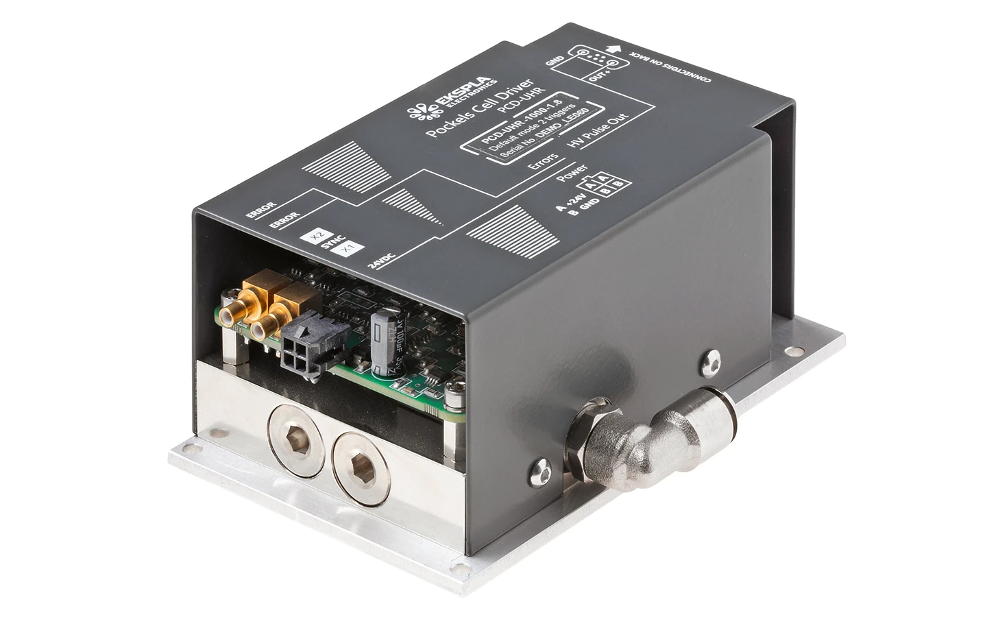
Fig 2a. Image of PCD-UHR-C Pockels cell drivers.
Models: PCD-UHR-50-3.6-C, PCD-UHR-250-2.6-C, PCD-UHR-250-3.6-C, PCD-UHR-400-1.5-C, PCD-UHR-500-2.6-C, PCD-UHR-1000-1. 8-C, PCD-UHR-2000-1.5-C.

Fig 2b. Drawings of PCD-UHR-C Pockels cell drivers.
Models: PCD-UHR-50-3.6-C, PCD-UHR-250-2.6-C, PCD-UHR-250-3.6-C, PCD-UHR-400-1.5-C, PCD-UHR-500-2.6-C, PCD-UHR-1000-1. 8-C, PCD-UHR-2000-1.5-C.

Fig 3a. Image of PCD-UHR-C-Option1 Pockels cell drivers.
Models: PCD-UHR-50-3.6-C-Option1, PCD-UHR-250-2.6-C-Option1, PCD-UHR-250-3.6-C-Option1, PCD-UHR-400-1.5-C-Option1, PCD-UHR-500-2.6-C-Option1, PCD-UHR-1000-1. 8-C-Option1, PCD-UHR-2000-1.5-C-Option1.

Fig 3b. Drawings of PCD-UHR-C-Option1 Pockels cell drivers.
Models: PCD-UHR-50-3.6-C-Option1, PCD-UHR-250-2.6-C-Option1, PCD-UHR-250-3.6-C-Option1, PCD-UHR-400-1.5-C-Option1, PCD-UHR-500-2.6-C-Option1, PCD-UHR-1000-1. 8-C-Option1, PCD-UHR-2000-1.5-C-Option1.

Fig 4a. Image of PCD-UHR-I-C Pockels cell drivers.
Models: PCD-UHR-I-250-5.2-C, PCD-UHR-I-300-4.6-C, PCD-UHR-I-350-4-C, PCD-UHR-I-1000-3.0-C.

Fig 4b. Drawings of PCD-UHR-I-C Pockels cell drivers.
Models: PCD-UHR-I-250-5.2-C, PCD-UHR-I-300-4.6-C, PCD-UHR-I-350-4-C, PCD-UHR-I-1000-3.0-C.

Fig 5a. Image of PCD-UHR-II and 2PCD-UHR-II Pockels cell drivers.
Models: PCD-UHR-II-150-7.0, 2PCD-UHR-II-300-3.4.

Fig 5b. Drawings of PCD-UHR-II and 2PCD-UHR-II Pockels cell drivers.
Models: PCD-UHR-II-150-7.0, 2PCD-UHR-II-300-3.4.

Fig 6a. Image of PCD-UHR-II-C and 2PCD-UHR-II-C Pockels cell drivers.
Models: PCD-UHR-II-250-7.0-C, PCD-UHR-II-1000-3.8-C, PCD-UHR-II-1000-4.0-C, 2PCD-UHR-II-500-3.4-C, 2PCD-UHR-II-1000-2.5-C, 2PCD-UHR-II-2000-1.8-C, 2PCD-UHR-II-2000-1.5-C.

Fig 6b. Drawings of PCD-UHR-II-C and 2PCD-UHR-II-C Pockels cell drivers.
Models: PCD-UHR-II-250-7.0-C, PCD-UHR-II-1000-3.8-C, PCD-UHR-II-1000-4.0-C, 2PCD-UHR-II-500-3.4-C, 2PCD-UHR-II-1000-2.5-C, 2PCD-UHR-II-2000-1.8-C, 2PCD-UHR-II-2000-1.5-C.

Fig 7a. Image of PCD-UHR-III-C and 2PCD-UHR-III-C Pockels cell drivers.
Models: PCD-UHR-III-500-7.2-C, PCD-UHR-III-2000-3.4-C, PCD-UHR-III-2500-3.1-C, PCD-UHR-III-3000-2.6-C, 2PCD-UHR-III-4000-1.7-C, 2PCD-UHR-III-6000-1.3-C.

Fig 7b. Drawings of PCD-UHR-III-C and 2PCD-UHR-III-C Pockels cell drivers.
Models: PCD-UHR-III-500-7.2-C, PCD-UHR-III-2000-3.4-C, PCD-UHR-III-2500-3.1-C, PCD-UHR-III-3000-2.6-C, 2PCD-UHR-III-4000-1.7-C, 2PCD-UHR-III-6000-1.3-C.

Fig 8a. Image of 2PCD-UHR-C Pockels cell drivers.
Models: 2PCD-UHR-500-3.4-C, 2PCD-UHR-1000-2.4-C, 2PCD-UHR-2000-1.6-C.

Fig 8b. Drawings of 2PCD-UHR-C Pockels cell drivers.
Models: 2PCD-UHR-500-3.4-C, 2PCD-UHR-1000-2.4-C, 2PCD-UHR-2000-1.6-C.

Fig 9a. Image of PCD-UHRS Pockels cell drivers.
Models: PCD-UHRS-50-3.6, PCD-UHRS-250-3.6, PCD-UHRS-250-2.6, PCD-UHRS-400-1.5, PCD-UHRS-500-2.6, PCD-UHRS-1000-1.8.

Fig 9b. Drawings of PCD-UHRS Pockels cell drivers.
Models: PCD-UHRS-50-3.6, PCD-UHRS-250-3.6, PCD-UHRS-250-2.6, PCD-UHRS-400-1.5, PCD-UHRS-500-2.6, PCD-UHRS-1000-1.8.
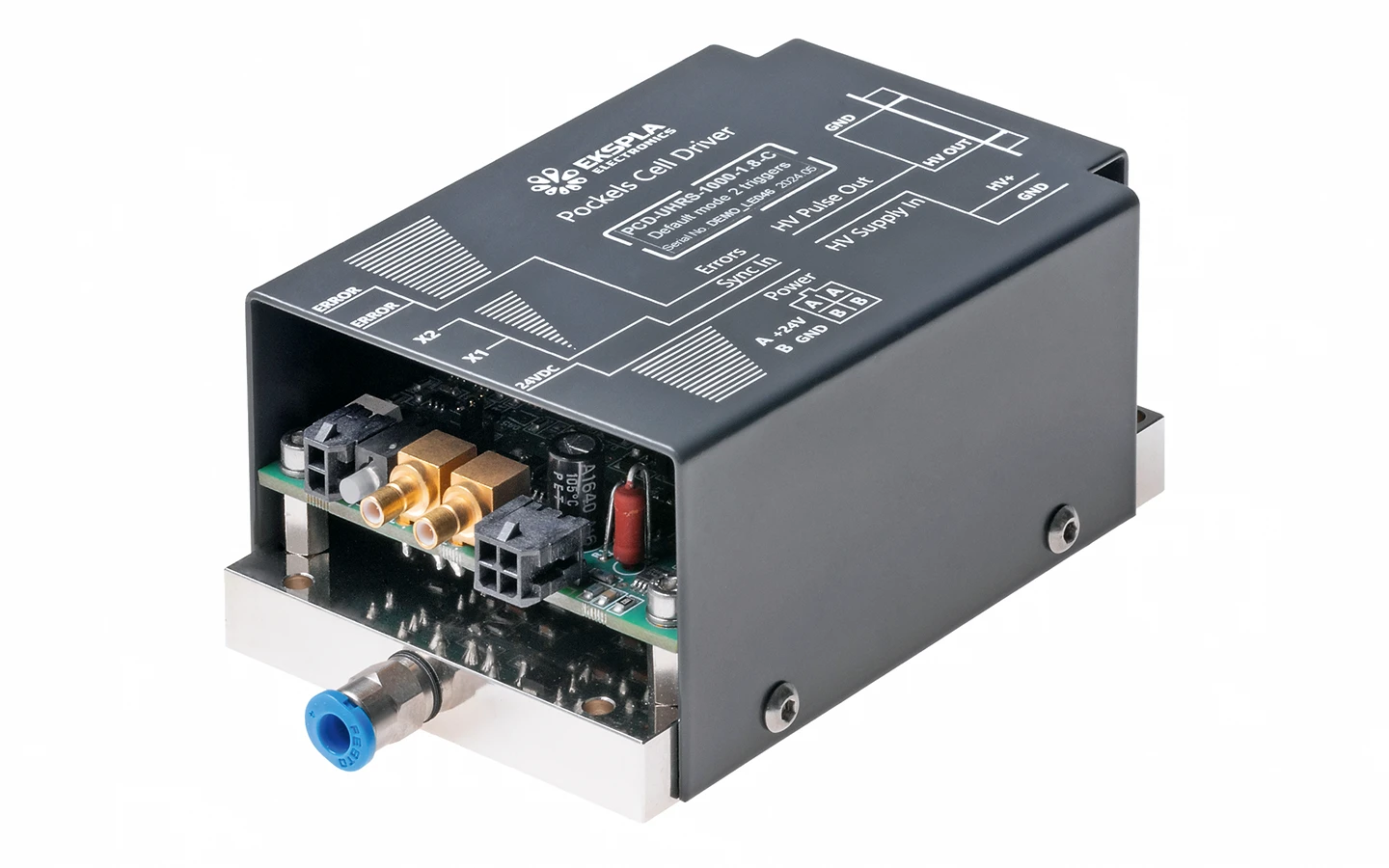
Fig 10a. Image of PCD-UHRS-C-Option1 Pockels cell drivers.
Models: PCD-UHRS-50-3.6-C-Option1, PCD-UHRS-250-3.6-C-Option1, PCD-UHRS-500-2.6-C-Option1, PCD-UHRS-1000-1. 8-C-Option1.

Fig 10b. Drawings of PCD-UHRS-C-Option1 Pockels cell drivers.
Models: PCD-UHRS-50-3.6-C-Option1, PCD-UHRS-250-3.6-C-Option1, PCD-UHRS-500-2.6-C-Option1, PCD-UHRS-1000-1. 8-C-Option1.

Fig 11a. Image of PCD-UHRS-C Pockels cell drivers.
Models: PCD-UHRS-50-3.6-C, PCD-UHRS-250-3.6-C, PCD-UHRS-500-2.6-C, PCD-UHRS-1000-1. 8-C.

Fig 11b. Drawings of PCD-UHRS-C Pockels cell drivers.
Models: PCD-UHRS-50-3.6-C, PCD-UHRS-250-3.6-C, PCD-UHRS-500-2.6-C, PCD-UHRS-1000-1. 8-C.

Fig 12a. Image of PCD-UHV Pockels cell drivers.
Models: PCD-UHV-4.2, PCD-UHV-5.5, PCD-UHV10-8.6, PCD-UHV10-9.8.

Fig 12b. Drawings of PCD-UHV Pockels cell drivers.
Models: PCD-UHV-4.2, PCD-UHV-5.5, PCD-UHV10-8.6, PCD-UHV10-9.8.
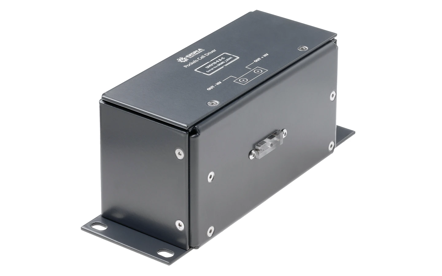
Fig 13a. Image of PCD-UHV-C Pockels cell drivers.
Models: PCD-UHV-4.2-C, PCD-UHV-5.5-C PCD-UHV10-8.6-C, PCD-UHV10-9.8-C.

Fig 13b. Drawings of PCD-UHV-C Pockels cell drivers.
Models: PCD-UHV-4.2-C, PCD-UHV-5.5-C PCD-UHV10-8.6-C, PCD-UHV10-9.8-C.

Fig 14a. Image of PCD-FAM-C Pockels cell drivers.
Models: PCD-FAM-250-2.5-C, PCD-FAM-500-2.5-C.

Fig 14b. Drawings of PCD-FAM-C Pockels cell drivers.
Models: PCD-FAM-250-2.5-C, PCD-FAM-500-2.5-C.

Fig 15a. Image of high power encased HV power supply.
Models: HV-200, HV-400, HV-2×200.
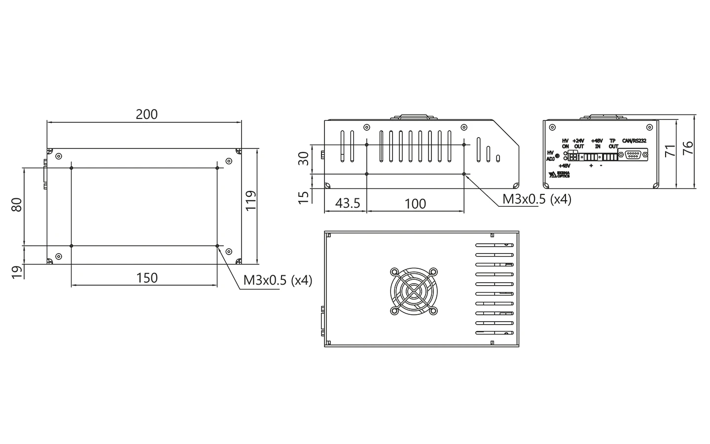
Fig 15b. Drawings of high power encased HV power supply.
Models: HV-200, HV-400, HV-2×200.

Fig 16a. Image of encased HV power supply.
Models: HV-170, HV-2×85.

Fig 16b. Drawings of encased HV power supply.
Models: HV-170, HV-2×85.
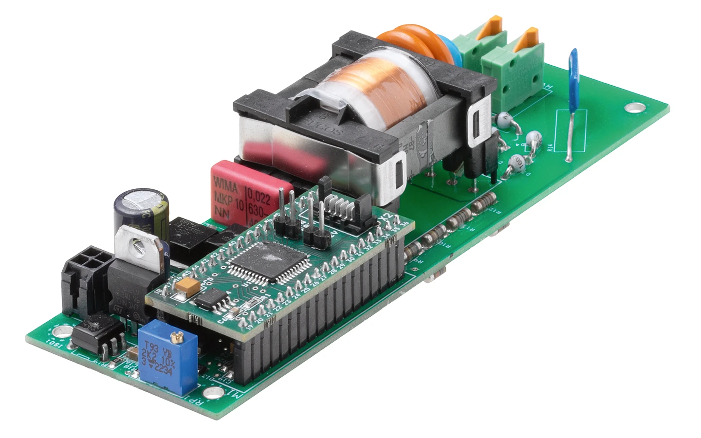
Fig 17a. Image of open frame HV05Wm power supply.
Models: HV05Wm, HV05Wm-CAN.

Fig 17a. Drawings of open frame HV05Wm power supply.
Models: HV05Wm, HV05Wm-CAN.

Fig 18a. Image of open frame HV40Wm power supply.
Models: HV40Wm, HV40Wm-CAN.

Fig 18b. Drawings of open frame HV40Wm power supply.
Models: HV40Wm, HV40Wm-CAN.

Fig 19a. Image of open frame HV80Wm power supply.
Models: HV80Wm, HV80Wm-CAN.

Fig 19b. Drawings of open frame HV80Wm power supply.
Models: HV80Wm, HV80Wm-CAN.

Fig 20a. Image of open frame HV120Wm power supply.
Models: HV120Wm, HV120Wm-CAN, HV2x60Wm, HV2x60Wm-CAN.

Fig 20b. Drawings of open frame HV120Wm power supply.
Models: HV120Wm, HV120Wm-CAN, HV2x60Wm, HV2x60Wm-CAN.
