Ultra-stable and high power laser diode drivers with internal TEC controller option uniLDD
Ultra-stable and high power laser diode drivers with internal TEC controller option
Laser diode drivers, also known as laser diode controllers, for pumping of diode pumped solid state lasers (DPSSL) as well as powering and beam modulation of direct diode lasers for vast variety of industrial, medical, scientific and military applications.

Features
- Current range from 10 A to 1200 A
- Compliance voltage range from 1 V to 600 V
- Current stability of < 0.1% pk to pk
- Current ripple of < 0.1% pk to pk
- Output power up to 6 kW
- Protections:
- current transient (overload) protection;
- open circuit shut-down;
- over temperature shut-down;
- power voltage brownout (voltage dip) shut-down;
- interlock shut-down
- Drivers can function simultaneously as TEC controllers and LDD current sources
- Can be controlled via analog and digital (CAN, RS232) interfaces.
- Uniquely customizable modular design ensures drivers can be tailored to precisely meet OEM customer’s needs
- Fast turnaround times between inquiry, prototyping and high-volume manufacturing stages
Applications
EKSPLA laser diode drivers are optimal for pumping of femtosecond, picosecond, nanosecond and CW solid state lasers based on crystal, fiber or direct-diode technology. Most popular fields of applications are:
- Industrial lasers
micromachining, welding and cutting - Medical lasers
ophthalmology, dermatology and surgery - Scientific lasers
fusion research, spectroscopy, and high-energy physics
Performance

Typical ripple current of uniLDD-A-CW.
12 V and 24 V DC power, 2 V junction + 10 MΩ series R load.

Typical current drift and long term stability of uniLDD-A-CW.
From cold start for different currents.

Peak performance example of custom Tri-uniLDD-A-QCW.
Iout 1195 A, Uout 473 V, PW 500 us, f 10 Hz, rise 36 µs, fall 14 µs, overshoot 0.7%.

uniLDD models coding scheme.
| Model | uniLDD-C-CW | uniLDD-C-QCW CW mode | uniLDD-C-QCW QCW mode |
|---|---|---|---|
| Output specifications 1) | |||
| Operation mode | CW 2) | CW 2) | QCW 3) |
| Compliance voltage range, min-max 4) | 1 – 90 V 5) | 1 – 90 V | 1 – 85 V |
| Current range, min-max | 10 – 100 A 6) | 10 – 100 A | 10 – 160 A |
| Average power, max | 3 kW 5) | 3 kW | 3 kW |
| Power conversion efficiency | 90 – 98 % | 90 – 98 % | 90 – 98 % |
| Current pulse amplitude stability | < 0.1 % pk to pk 7) | < 0.1 % pk to pk 7) | < 0.1 % pk to pk 7) |
| Current ripple | < 0.1 % pk to pk 8) | < 0.1 % pk to pk 8) | < 0.1 % pk to pk 8) |
| Current drift | < 0.2 % 9) | < 0.2 % 9) | < 0.2 % 9) |
| Duty cycle | – | – | ≤ 20 % |
| Repetition rate, max | – | – | ≤ 5 kHz |
| Current rise time, typical | – | – | 5 – 100 μs 10) |
| Current pulse duration, typical | – | – | up to 100 ms 11) |
| RMS current, max | – | – | 100 A |
| Amount of functioning internal TEC control channels | 0, 1 or 2 12) | 0, 1 or 2 12) | 0, 1 or 2 12) |
| TEC control current, min-max per channel | 1 – 25 A | 1 – 25 A | 1 – 25 A |
| TEC control voltage, min-max per channel | 1 – 36 V | 1 – 36 V | 1 – 36 V |
| TEC control power, max per channel | 350 W | 350 W | 350 W |
| Input specifications | |||
| Power supply requirements (power stage), min | UPS in min (V) = ULDD out max + 5 PPS in min (W) = ILDD out max * ULDD out max * duty cyclemax / 100 % * 1.2 | UPS in min (V) = ULDD out max + 5 PPS in min (W) = ILDD out max * ULDD out max * duty cyclemax / 100 % * 1.2 | UPS in min (V) = ULDD out max + 5 PPS in min (W) = ILDD out max * ULDD out max * duty cyclemax / 100 % * 1.2 |
| Power supply requirements (control stage) | 12 V, 10 W | 12 V, 10 W | 12 V, 10 W |
| Control interfaces | analog, CAN & RS232 by default. USB, LAN & WLAN upon request 13) | analog, CAN & RS232 by default. USB, LAN & WLAN upon request 13) | analog, CAN & RS232 by default. USB, LAN & WLAN upon request 13) |
| Software | Ekspla’s control software 14) | Ekspla’s control software 14) | Ekspla’s control software 14) |
| Protections | current transient (overload) protection; open circuit shut-down; over temperature shut-down; power voltage brownout (voltage dip) shut-down; interlock shut-down | current transient (overload) protection; open circuit shut-down; over temperature shut-down; power voltage brownout (voltage dip) shut-down; interlock shut-down | current transient (overload) protection; open circuit shut-down; over temperature shut-down; power voltage brownout (voltage dip) shut-down; interlock shut-down |
| Physical characteristics | |||
| Dimensions (L x W x H) 15) | 130 x 90 x 30 mm | 130 x 90 x 54 mm | 130 x 90 x 54 mm |
| Operating requirements | |||
| Cooling method | Conductive | Conductive | Conductive |
| Operating ambient temperature | ≤ 40 °C | ≤ 40 °C | ≤ 40 °C |
| Operating baseplate temperature | ≤ 50 °C | ≤ 50 °C | ≤ 50 °C |
| Accessories | |||
| CAN-USB adapter | on request. Required at evaluation stage 16) | on request. Required at evaluation stage 16) | on request. Required at evaluation stage 16) |
| Communication board | on request. For driver control via RS232, USB, LAN, WLAN interfaces 17) | on request. For driver control via RS232, USB, LAN, WLAN interfaces 17) | on request. For driver control via RS232, USB, LAN, WLAN interfaces 17) |
| Voltage booster board | on request 5) | on request 5) | on request 5) |
| Baseplate | copper, included by default | copper, included by default | copper, included by default |
| Output power cables | included upon request, custom dia and length | included upon request, custom dia and length | included upon request, custom dia and length |
| Input power cables | included upon request, custom dia and length | included upon request, custom dia and length | included upon request, custom dia and length |
| Control cables | included by default | included by default | included by default |
| External capacitors | on request 18) | on request 18) | on request 18) |
| Model | uniLDD-C-CW | uniLDD-C-QCW CW mode | uniLDD-C-QCW QCW mode |
|---|
- Due to continuous improvement, all specifications are subject to change without notice. Parameters marked typical are not specifications. They are indications of typical performance and will vary with each unit we manufacture.
- Continuous-wave.
- Quasi-continuous-wave (also known as pulsed).
- Range between minimum and maximum limits. Not all maximal limits can be reached simultaneously.
- Maximum compliance voltage and maximum power can be extended for certain versions by using booster board layout. Ekspla’s booster board which allows to extend output compliance voltage of certain uniLDD versions. In certain cases output compliance voltage can be increased up to 600 V. Can be added at factory upon Ekspla’s recommendations.
- Maximum current can be extended for certain versions by connecting drivers in parallel.
- In ×0.5…×1 of max current range.
- DC…100 kHz bandwidth, in ×0.5…×1 of max current range.
- Cold start, 8 h period, after 5 min. warm up.
- Factory software tuned upon customer’s request.
- Factory software & hardware tuned upon customer’s request.
- Amount factory enabled upon customer’s request.
- USB, LAN & WLAN control interfaces are available upon customer’s request while using Ekspla’s external communication board.
- Ekspla’s control software & protocol description included by default.
- External driver dimensions can vary ± 20 mm due to the minor hardware variations like fans and current sensors.
- Ekspla’s CAN-USB adapter is required at evaluation stage if communication via CAN interface is needed.
- Ekspla’s communication board allows to control driver via RS232, USB, LAN, WLAN interfaces. Can be provided upon request.
- Included upon Ekspla’s recommentadion. Custom mounting solutions for external capacitor are available upon request.
| Model | uniLDD-A-CW | uniLDD-A-QCW CW mode | uniLDD-A-QCW QCW mode |
|---|---|---|---|
| Output specifications 1) | |||
| Operation mode | CW 2) | CW 2) | QCW 3) |
| Compliance voltage range, min-max 4) | 1 – 85 V | 1 – 90 V 5) | 1 – 85 V |
| Current range, min-max | 10 – 100 A | 10 – 100 A 6) | 10 – 360 A |
| Power, max | 2 kW | 2 kW 5) | 2 kW |
| Power conversion efficiency | 90 – 98 % | 90 – 98 % | 90 – 98 % |
| Current pulse amplitude stability | < 0.1 % pk to pk 7) | < 0.1 % pk to pk 7) | < 0.1 % pk to pk 7) |
| Current ripple | < 0.1 % pk to pk 8) | < 0.1 % pk to pk 8) | < 0.1 % pk to pk 8) |
| Current drift | < 0.2 % 9) | < 0.2 % 9) | < 0.2 % 9) |
| Duty cycle | – | – | ≤ 20 % |
| Repetition rate, max | – | – | ≤ 5 kHz |
| Current rise time, typical | – | – | 5 – 100 μs |
| Current pulse duration, typical | – | – | up to 100 ms |
| RMS current, max | – | – | 80 A |
| Amount of functioning internal TEC control channels | 0, 1 or 2 10) | 0, 1 or 2 10) | 0, 1 or 2 10) |
| TEC control current, min-max per channel | 1 – 25 A | 1 – 25 A | 1 – 25 A |
| TEC control voltage, min-max per channel | 1 – 36 V | 1 – 36 V | 1 – 36 V |
| TEC control power, max per channel | 350 W | 350 W | 350 W |
| Input specifications | |||
| Power supply requirements (power stage), min | UPS in min (V) = ULDD out max + 5 PPS in min (W) = ILDD out max * ULDD out max * duty cyclemax / 100 % * 1.2 | UPS in min (V) = ULDD out max + 5 PPS in min (W) = ILDD out max * ULDD out max * duty cyclemax / 100 % * 1.2 | UPS in min (V) = ULDD out max + 5 PPS in min (W) = ILDD out max * ULDD out max * duty cyclemax / 100 % * 1.2 |
| Power supply requirements (control stage) | 12 V, 10 W | 12 V, 10 W | 12 V, 10 W |
| Control interfaces | analog, CAN & RS232 by default. USB, LAN & WLAN upon request 11) | analog, CAN & RS232 by default. USB, LAN & WLAN upon request 11) | analog, CAN & RS232 by default. USB, LAN & WLAN upon request 11) |
| Software | Ekspla’s control software 12) | Ekspla’s control software 12) | Ekspla’s control software 12) |
| Protections | current transient (overload) protection; open circuit shut-down; over temperature shut-down; power voltage brownout (voltage dip) shut-down; interlock shut-down | current transient (overload) protection; open circuit shut-down; over temperature shut-down; power voltage brownout (voltage dip) shut-down; interlock shut-down | current transient (overload) protection; open circuit shut-down; over temperature shut-down; power voltage brownout (voltage dip) shut-down; interlock shut-down |
| Physical characteristics | |||
| Dimensions (L x W x H) 13) | 208 x 65 x 103 mm | 208 x 65 x 103 mm | 208 x 65 x 103 mm |
| Operating requirements | |||
| Cooling method | Forced-air | Forced-air | Forced-air |
| Operating ambient temperature | ≤ 40 °C | ≤ 40 °C | ≤ 40 °C |
| Accessories | |||
| CAN-USB adapter | on request. Required at evaluation stage 14) | on request. Required at evaluation stage 14) | on request. Required at evaluation stage 14) |
| Communication board | on request. For driver control via RS232, USB, LAN, WLAN interfaces 15) | on request. For driver control via RS232, USB, LAN, WLAN interfaces 15) | on request. For driver control via RS232, USB, LAN, WLAN interfaces 15) |
| Voltage booster board | on request 5) | on request 5) | on request 5) |
| Baseplate | aluminum, included upon request | aluminum, included upon request | aluminum, included upon request |
| Output power cables | included upon request, custom dia and length | included upon request, custom dia and length | included upon request, custom dia and length |
| Input power cables | included upon request, custom dia and length | included upon request, custom dia and length | included upon request, custom dia and length |
| Control cables | included by default | included by default | included by default |
| External capacitors | on request 16) | on request 16) | on request 16) |
| Model | uniLDD-A-CW | uniLDD-A-QCW CW mode | uniLDD-A-QCW QCW mode |
|---|
- Due to continuous improvement, all specifications are subject to change without notice. Parameters marked typical are not specifications. They are indications of typical performance and will vary with each unit we manufacture.
- Continuous-wave.
- Quasi-continuous-wave (also known as pulsed).
- Range between minimum and maximum limits. Not all maximal limits can be reached simultaneously.
- Maximum compliance voltage and maximum power can be extended for certain versions by using booster board layout. Ekspla’s booster board which allows to extend output compliance voltage of certain uniLDD versions. In certain cases output compliance voltage can be increased up to 600 V. Can be added at factory upon Ekspla’s recommendations.
- Maximum current can be extended for certain versions by connecting drivers in parallel.
- In ×0.5…×1 of max current range.
- DC…100 kHz bandwidth, in ×0.5…×1 of max current range.
- Cold start, 8 h period, after 5 min. warm up.
- Amount factory enabled upon customer’s request.
- USB, LAN & WLAN control interfaces are available upon customer’s request while using Ekspla’s external communication board.
- Ekspla’s control software & protocol description included by default.
- External driver dimensions can vary ± 20 mm due to the minor hardware variations like fans and current sensors.
- Ekspla’s CAN-USB adapter is required at evaluation stage if communication via CAN interface is needed.
- Ekspla’s communication board allows to control driver via RS232, USB, LAN, WLAN interfaces. Can be provided upon request.
- Included upon Ekspla’s recommentadion. Custom mounting solutions for external capacitor are available upon request.
| Model | Bi-uniLDD-A-QCW CW mode | Bi-uniLDD-A-QCW QCW mode | Tri-uniLDD-A-QCW CW mode | Tri-uniLDD-A-QCW QCW mode |
|---|---|---|---|---|
| Output specifications 1) | ||||
| Operation mode | CW 2) | QCW 3) | CW 2) | QCW 3) |
| Compliance voltage range, min-max 4) | 1 – 90 V | 1 – 85 V | 1 – 90 V | 1 – 85 V |
| Current range, min-max | 20 – 200 A | 20 – 800 A | 30 – 300 A | 30 – 1200 A |
| Power, max | 4 kW | 4 kW | 6 kW | 6 kW |
| Power conversion efficiency | 90 – 98 % | 90 – 98 % | 90 – 98 % | 90 – 98 % |
| Current pulse amplitude stability | < 0.1 % pk to pk 5) | < 0.1 % pk to pk 5) | < 0.1 % pk to pk 5) | < 0.1 % pk to pk 5) |
| Current ripple | < 0.1 % pk to pk 6) | < 0.1 % pk to pk 6) | < 0.1 % pk to pk 6) | < 0.1 % pk to pk 6) |
| Current drift | < 0.2 % 7) | < 0.2 % 7) | < 0.2 % 7) | < 0.2 % 7) |
| Duty cycle | – | ≤ 20 % | – | ≤ 20 % |
| Repetition rate, max | – | ≤ 5 kHz | – | ≤ 5 kHz |
| Current rise time, typical | – | 5 – 100 μs | – | 5 – 100 μs |
| Current pulse duration, typical | – | up to 100 ms | – | up to 100 ms |
| RMS current, max | – | 160 A | – | 240 A |
| Amount of functioning internal TEC control channels | 0 | 0 | 0 | 0 |
| Input specifications | ||||
| Power supply requirements (power stage), min | UPS in min (V) = ULDD out max + 5 PPS in min (W) = ILDD out max * ULDD out max * duty cyclemax / 100 % * 1.2 | UPS in min (V) = ULDD out max + 5 PPS in min (W) = ILDD out max * ULDD out max * duty cyclemax / 100 % * 1.2 | UPS in min (V) = ULDD out max + 5 PPS in min (W) = ILDD out max * ULDD out max * duty cyclemax / 100 % * 1.2 | UPS in min (V) = ULDD out max + 5 PPS in min (W) = ILDD out max * ULDD out max * duty cyclemax / 100 % * 1.2 |
| Power supply requirements (control stage) | 12 V, 20 W | 12 V, 20 W | 12 V, 25 W | 12 V, 25 W |
| Control interfaces | analog, CAN & RS232 by default. USB, LAN & WLAN upon request 8) | analog, CAN & RS232 by default. USB, LAN & WLAN upon request 8) | analog, CAN & RS232 by default. USB, LAN & WLAN upon request 8) | analog, CAN & RS232 by default. USB, LAN & WLAN upon request 8) |
| Software | Ekspla’s control software 9) | Ekspla’s control software 9) | Ekspla’s control software 9) | Ekspla’s control software 9) |
| Protections | current transient (overload) protection; open circuit shut-down; over temperature shut-down; power voltage brownout (voltage dip) shut-down; interlock shut-down | current transient (overload) protection; open circuit shut-down; over temperature shut-down; power voltage brownout (voltage dip) shut-down; interlock shut-down | current transient (overload) protection; open circuit shut-down; over temperature shut-down; power voltage brownout (voltage dip) shut-down; interlock shut-down | current transient (overload) protection; open circuit shut-down; over temperature shut-down; power voltage brownout (voltage dip) shut-down; interlock shut-down |
| Physical characteristics | ||||
| Dimensions (L x W x H) 10) | 250 x 146 x 98 mm | 250 x 146 x 98 mm | 250 x 200 x 98 mm | 250 x 200 x 98 mm |
| Operating requirements | ||||
| Cooling method | Forced-air | Forced-air | Forced-air | Forced-air |
| Operating ambient temperature | ≤ 40 °C | ≤ 40 °C | ≤ 40 °C | ≤ 40 °C |
| Accessories | ||||
| CAN-USB adapter | on request. Required at evaluation stage 11) | on request. Required at evaluation stage 11) | on request. Required at evaluation stage 11) | on request. Required at evaluation stage 11) |
| Communication board | on request. For driver control via RS232, USB, LAN, WLAN interfaces 12) | on request. For driver control via RS232, USB, LAN, WLAN interfaces 12) | on request. For driver control via RS232, USB, LAN, WLAN interfaces 12) | on request. For driver control via RS232, USB, LAN, WLAN interfaces 12) |
| Voltage booster board | on request 13) | on request 13) | on request 13) | on request 13) |
| Baseplate | aluminum, included by default | aluminum, included by default | aluminum, included by default | aluminum, included by default |
| Output power cables | included upon request, custom dia and length | included upon request, custom dia and length | included upon request, custom dia and length | included upon request, custom dia and length |
| Input power cables | included upon request, custom dia and length | included upon request, custom dia and length | included upon request, custom dia and length | included upon request, custom dia and length |
| Control cables | included by default | included by default | included by default | included by default |
| External capacitors | on request 14) | on request 14) | on request 14) | on request 14) |
| Model | Bi-uniLDD-A-QCW CW mode | Bi-uniLDD-A-QCW QCW mode | Tri-uniLDD-A-QCW CW mode | Tri-uniLDD-A-QCW QCW mode |
|---|
- Due to continuous improvement, all specifications are subject to change without notice. Parameters marked typical are not specifications. They are indications of typical performance and will vary with each unit we manufacture.
- Continuous-wave.
- Quasi-continuous-wave (also known as pulsed).
- Range between minimum and maximum limits. Not all maximal limits can be reached simultaneously.
- In ×0.5…×1 of max current range.
- DC…100 kHz bandwidth, in ×0.5…×1 of max current range.
- Cold start, 8 h period, after 5 min. warm up.
- USB, LAN & WLAN control interfaces are available upon customer’s request while using Ekspla’s external communication board.
- Ekspla’s control software & protocol description included by default.
- External driver dimensions can vary ± 20 mm due to the minor hardware variations like fans and current sensors.
- Ekspla’s CAN-USB adapter is required at evaluation stage if communication via CAN interface is needed.
- Ekspla’s communication board allows to control driver via RS232, USB, LAN, WLAN interfaces. Can be provided upon request.
- Maximum compliance voltage and maximum power can be extended for certain versions by using booster board layout. Ekspla’s booster board which allows to extend output compliance voltage of certain uniLDD versions. In certain cases output compliance voltage can be increased up to 600 V. Can be added at factory upon Ekspla’s recommendations.
- Included upon Ekspla’s recommentadion. Custom mounting solutions for external capacitor are available upon request.
| Pin | Signal name | Direction | Voltage level | Description |
|---|---|---|---|---|
| 1 | Enable | Input | TTL (LVTTL) 200 µA pull up to 3.3 V | The Enable function gives permission to operate for TEC driver and consequently for LDD driver. |
| 2 | Ready To Operate (RTO) | Input/Output through 330 Ω resistor | 2.4 V driver output is active, < 0.5 V output is clamped | RTO is tied to ‘High’ by the driver when ‘Active RTO ‘ is enabled and the driver is in active state. Alarms clamp RTO low and disable driver output. External device may clamp RTO to GND and disable driver output. RTO allows to join fault circuits of several drivers connected in parallel |
| 3 | Interlock | Input | 10 kΩ pull up to 3.3 V, LOW = < 0.4 V | The Interlock function can be connected to external safety or machine protection switches such as door or temperature switches. Open = OFF Connect to GND = RUN |
| 4 | GND | |||
| 5 | Vout monitor | Output | Vout, driver output voltage | The output voltage monitor. Vout = Diode compliance voltage + voltage drop on connection wires |
| 6 | Iout monitor | Output | 0 – 10 V* = 0 – Ioutmax | The output current monitor |
| 7 | Iprogram | Input | 0 – 10 V* = 0 – Ioutmax | Output current setting or modulating by applying a voltage, CW and Pulse mode |
| 8 | Pulse control | Input | TTL, LVTTL positive pulse | In TriggerIN mode: trigger input. A rising pulse provided to this connector will trigger an output current pulse of a preset width. In Time-gated mode: input to start/stop the output current.” Connection “Trigger input” performs the same function |
| 9 | GND | |||
| 10 | +5V | Output | Auxiliary 200 mA | |
| 11 | +5V | Output | Auxiliary 200 mA | |
| 12 | -15V | Output | Auxiliary 200 mA | |
| 13 | +15V | Output | Auxiliary 200 mA | |
| 14 | +15V | Output | Auxiliary 200 mA | |
| 15 | GND |
| Pin | Signal name | Direction | Voltage level | Description |
|---|
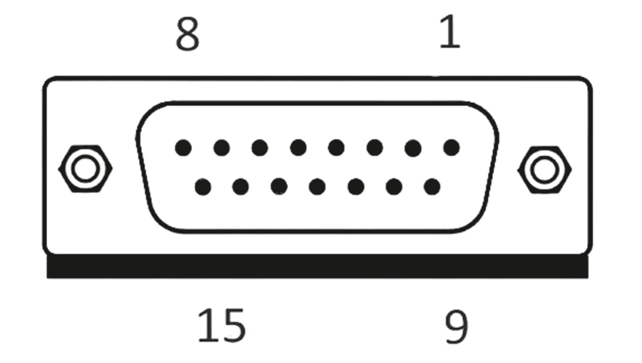
D-sub 15-pin female analog interface connector.

Image of uniLDD-C-CW.

Drawings of uniLDD-C-CW.
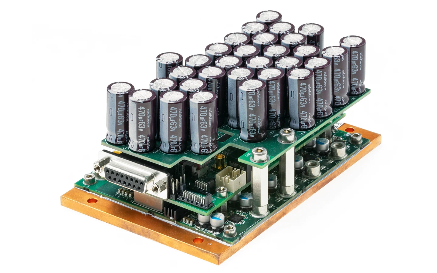
Image of uniLDD-C-QCW.

Drawings of uniLDD-C-QCW.

Image of uniLDD-A-CW.
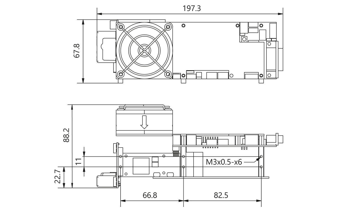
Drawings of uniLDD-A-CW.

Image of uniLDD-A-QCW.

Drawings of uniLDD-A-QCW.
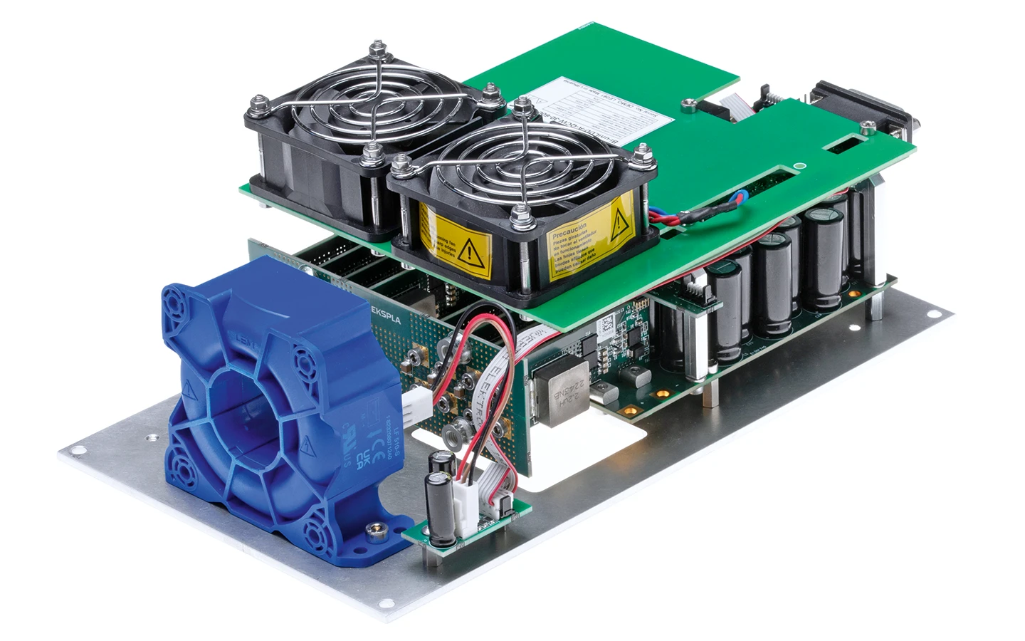
Image of Bi-uniLDD-A-QCW.

Drawings of Bi-uniLDD-A-QCW.
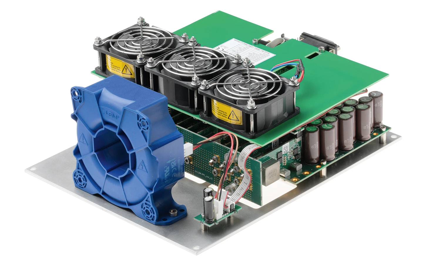
Image of Tri-uniLDD-A-QCW.

Drawings of Tri-uniLDD-A-QCW.