
Digital delay generator SY4000
Digital delay generator
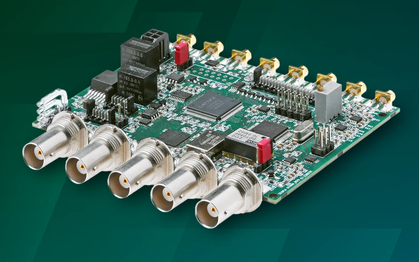
The digital delay generator SY4000 is designed to create up to 8 delayed output pulse sequences precisely synchronized with the internal or external clock. Digital delay generators can provide precise delays for triggering, syncing, delaying, and gating events.
Features
- 8 independent output channels
- Ultra-stable internal clock 0.2 ppm
- Precise delay/pulse width control in range 2 ns to 150 ms
- 25 ps timing resolution
- Hi-accuracy synchronization (locking) to external pulse train
- Jitter < 30 ps
- DAC/AWG output
- Both 50 Ω (6 outs) and differential (8 outs) outputs present
- Frequency divider / Burst (software and hardware triggered) / Gating / Single shot
- Communications:
- OEM version – CAN BUS
- Encased version – LAN, WIFI (optional), RS232, USB (VCP) – via REST API or DLL’s.
Applications
- Mode locked and Q-switched fs, ps & ns lasers
- Triggering of a data acquisition system
- General purpose pulse generator
- Precise system clock source
- Laser pulse train conversion into a clean clock source
- All functions above at once
Description
The Ekspla’s digital delay generator SY4000 is designed to create up to 8 delayed output pulse sequences precisely synchronized with the internal or external clock. Digital delay generators can provide precise delays for triggering, syncing, delaying, and gating events.
Our SY4000 digital delay generator is mainly employed for synchronization and control of different laser components: AOM drivers, Pockels cell drivers, laser diode drivers, flash lamp drivers, photodetectors, data acquisition systems, etc.
Ekspla can provide both encased and OEM versions of SY4000 digital delay generator. The encased digital delay generator version can be controlled via RS232, USB, LAN, WLAN and also contains a user-friendly configuration software as well as an internal power supply. These communication options as well as software are also available in SY4000 digital delay generator’s OEM version and can be reached by adding additional Ekspla’s OEM communication board upon customer’s request. The encased digital delay generator is an optimal solution for laboratory use while SY4000 OEM version is ideal for integration and is frequently paired with an additional Ekspla’s OEM communication board.

SY4000 desktop version.
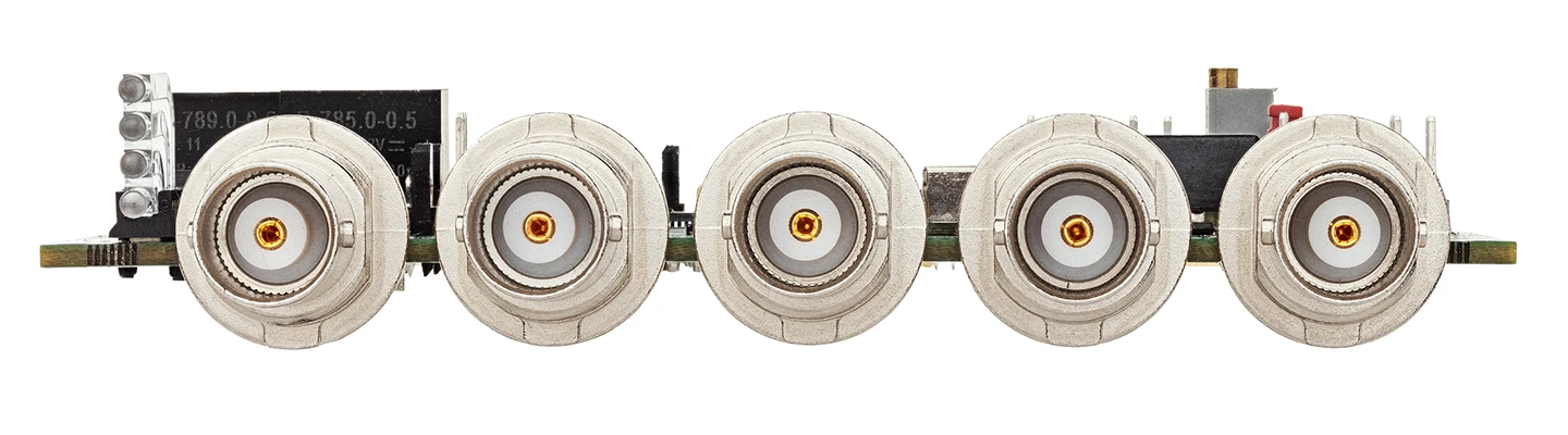
Coaxial connectors, A-side, BNC type.
OEM version of SY4000.
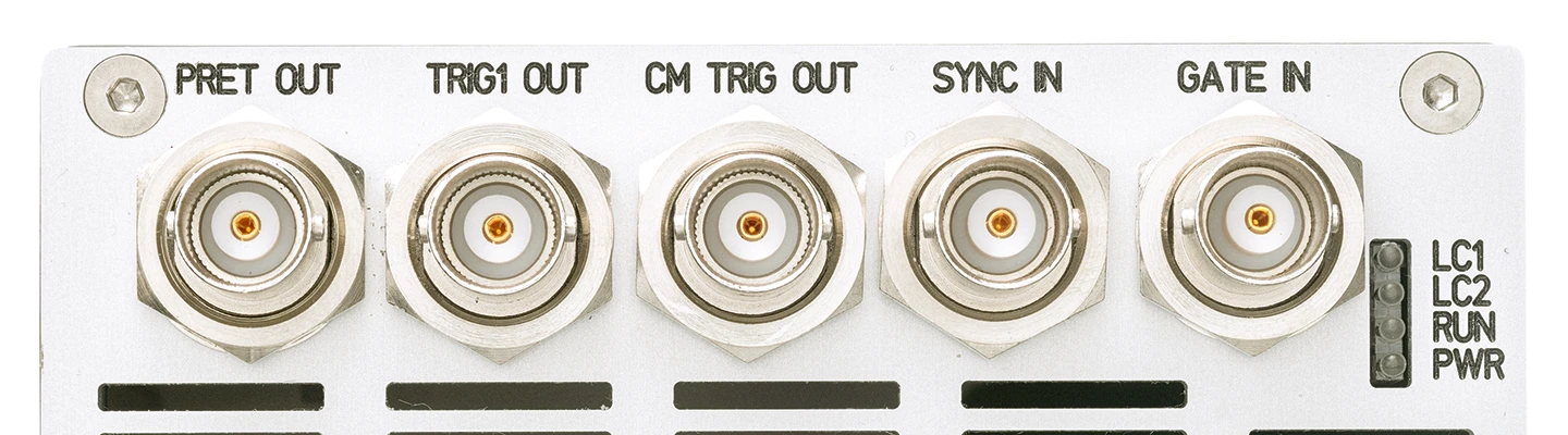
Coaxial connectors, A-side, BNC type.
Desktop version of SY4000.
| Name | PRET OUT | TRIG1 OUT | CM TRIG OUT | SYNC IN | GATE IN |
|---|---|---|---|---|---|
| Function | Precision trigger, configurable source | General trigger, configurable source | Master trigger, OUT0 signal | Trigger input | Configuration switch and burst control input |
| Description | Precise trigger, locked to the optical clock. Delay is adjustable in optical clock period time units. Jitter in respect to the optical pulse is ~4 ps RMS, almost independent on delay | General purpose or control sync out | Common trigger, general purpose output | External synchronization input. Trigger or Configuration switch source | Burst trigger or configuration switch control functions |
| Amplitude | >1 V on 50 Ω, AC output, capacitor @ output | 2.5 V @ 50 Ω | 2.5 V @ 50 Ω | LVTTL 0.1 mA pull down to low level | LVTTL, 0.1 mA pull down to low level |
| Pulse parameters | Rise time ~200 ps, width adjustable >100 ns | Select-able multiplexer to OUT0…OUT8 blocks, Optical clock, Optical clock/2 | OUT0 block, programmable pulse parameters | Frequency ≤ 100 MHz, PW ≥ 10 ns | Level or pulse with PW > 20 ns |
| Shape | Positive pulse | Logic level or pulse with programmable timing | Logic level or pulse with programmable timing | Positive pulse | Level or pulse |
| Direction | Output | Output | Output | Input | Input |
| Logic levels | 1.5 V @ 50 Ω | 2.5 V @ 50 Ω, 4.5 V @ 50 Ω jumper configurable | 2.5 V @ 50 Ω, 4.5 V @ 50 Ω jumper configurable | LVTTL, tolerates 5 V | LVTTL, tolerates 5 V |
| Impedance | 50 Ω | 50 Ω | 50 Ω | 0.2 mA pull down | 0.2 mA pull down |
| Name | PRET OUT | TRIG1 OUT | CM TRIG OUT | SYNC IN | GATE IN |
|---|

Coaxial connectors, B-side, MCX type.
OEM version of SY4000.
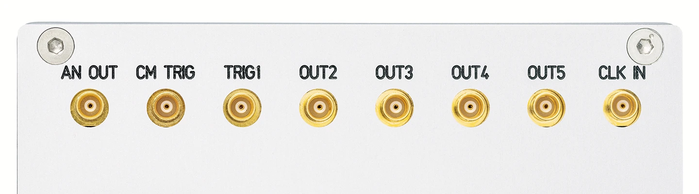
Coaxial connectors, B-side, MCX type.
Desktop version of SY4000.
| Name | AN OUT | CM TRIG OUT | CM TRIG OUT1 | OUT2 | OUT3 | OUT4 | OUT5 | CLC IN |
|---|---|---|---|---|---|---|---|---|
| Function | DAC analog output signal | Master trigger, OUT0 signal | Master trigger, OUT0 signal | General purpose trigger, OUT2 signal | General purpose trigger, OUT3 signal | General purpose trigger, OUT4 signal | General purpose trigger, OUT5 signal | Clock input |
| Description | DAC output | Common trigger, general purpose output | Common trigger, general purpose output | General purpose output | General purpose output | General purpose output | General purpose output | External clock input |
| Amplitude | 0…1 V | 2.5 V @ 50 Ω | 2.5 V @ 50 Ω | 2.5 V @ 50 Ω | 2.5 V @ 50 Ω | 2.5 V @ 50 Ω | 2.5 V @ 50 Ω | 100 mV |
| Pulse parameters | N/A | OUT0 block | OUT0 block | OUT2 block, AND+OR+NOT logic with OUT1 | OUT3 block, AND+OR+NOT logic with OUT2 | OUT4 block, AND+OR+NOT logic with OUT3 | OUT5 block, AND+OR+NOT logic with OUT4 | PW >300ps, input frequency 10…100 MHz |
| Shape | Two programmable analog levels | Logic level or pulse with programmable timing | Logic level or pulse with programmable timing | Logic level or pulse with programmable timing | Logic level or pulse with programmable timing | Logic level or pulse with programmable timing | Logic level or pulse with programmable timing | Sine, Meander to pulse train from photodiode |
| Direction | Output | Output | Output | Output | Output | Output | Output | Input |
| Logic levels | 1.5 V @ 50 Ω | 2.5 V @ 50 Ω, 4.5 V @ 50 Ω jumper configurable | 2.5 V @ 50 Ω, 4.5 V @ 50 Ω jumper configurable | 2.5 V @ 50 Ω, 4.5 V @ 50 Ω jumper configurable | 2.5 V @ 50 Ω, 4.5 V @ 50 Ω jumper configurable | 2.5 V @ 50 Ω, 4.5 V @ 50 Ω jumper configurable | 2.5 V @ 50 Ω, 4.5 V @ 50 Ω jumper configurable | 0.5 V…3.3 V pk-pk, sine or pulses |
| Impedance | 50 Ω | 50 Ω | 50 Ω | 50 Ω | 50 Ω | 50 Ω | 50 Ω | 50 Ω |
| Name | AN OUT | CM TRIG OUT | CM TRIG OUT1 | OUT2 | OUT3 | OUT4 | OUT5 | CLC IN |
|---|
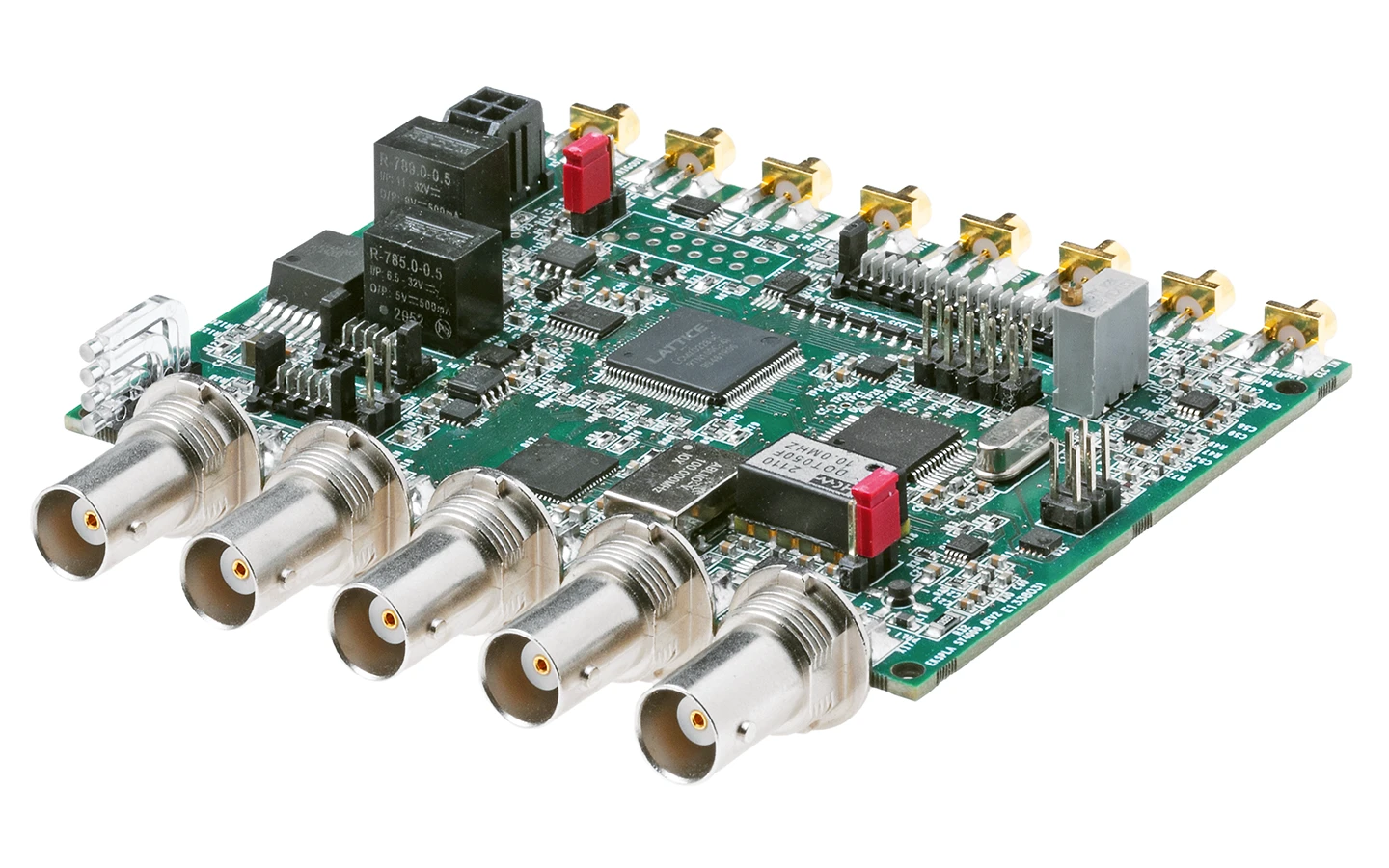
SY4000 OEM version.

Drawings of SY4000 OEM version.
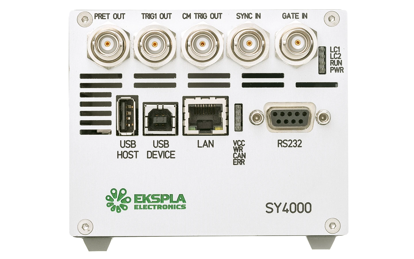
SY4000 desktop version.
Front view.
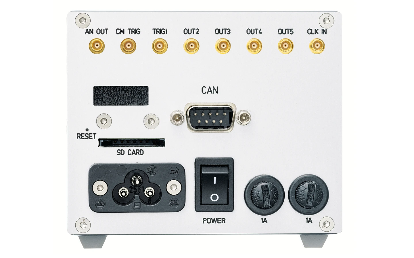
SY4000 desktop version.
Back view.
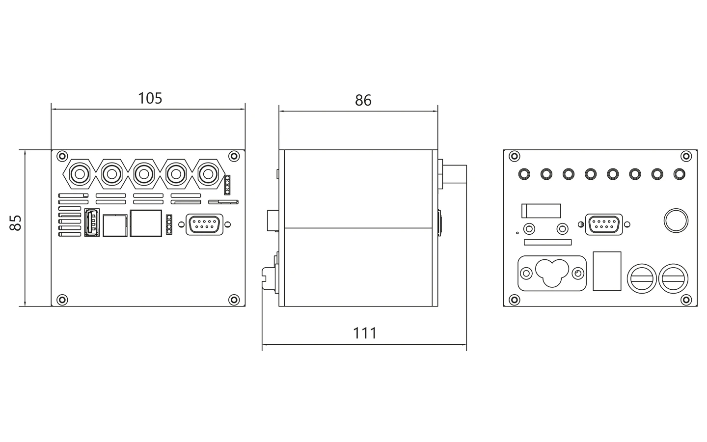
Drawings of SY4000 desktop version.
